Site Announcement
Sign up today and receive company updates straight to your inbox
Sign up today and receive company updates straight to your inbox
September 23, 2026
Large diameter rotary drilling is not a new capability. Between 1959 and 1970, American contractors drilled holes up to 120 inches in diameter to depths beyond 5,000 feet, using oilfield rigs, oilfield crews, and a circulation method, reverse flood, still in commercial service today. The technique never belonged to oil and gas production; its anchor customers were the American nuclear test program (initiated after the Limited Test Ban Treaty) and the mining industry. When the test program ended, the shaft and injection well markets that predated it carried the capability forward, and they are still drilling with it now.
Large-diameter drilling, 1901 to today. Reference numbers follow the paper.
| 1901 | 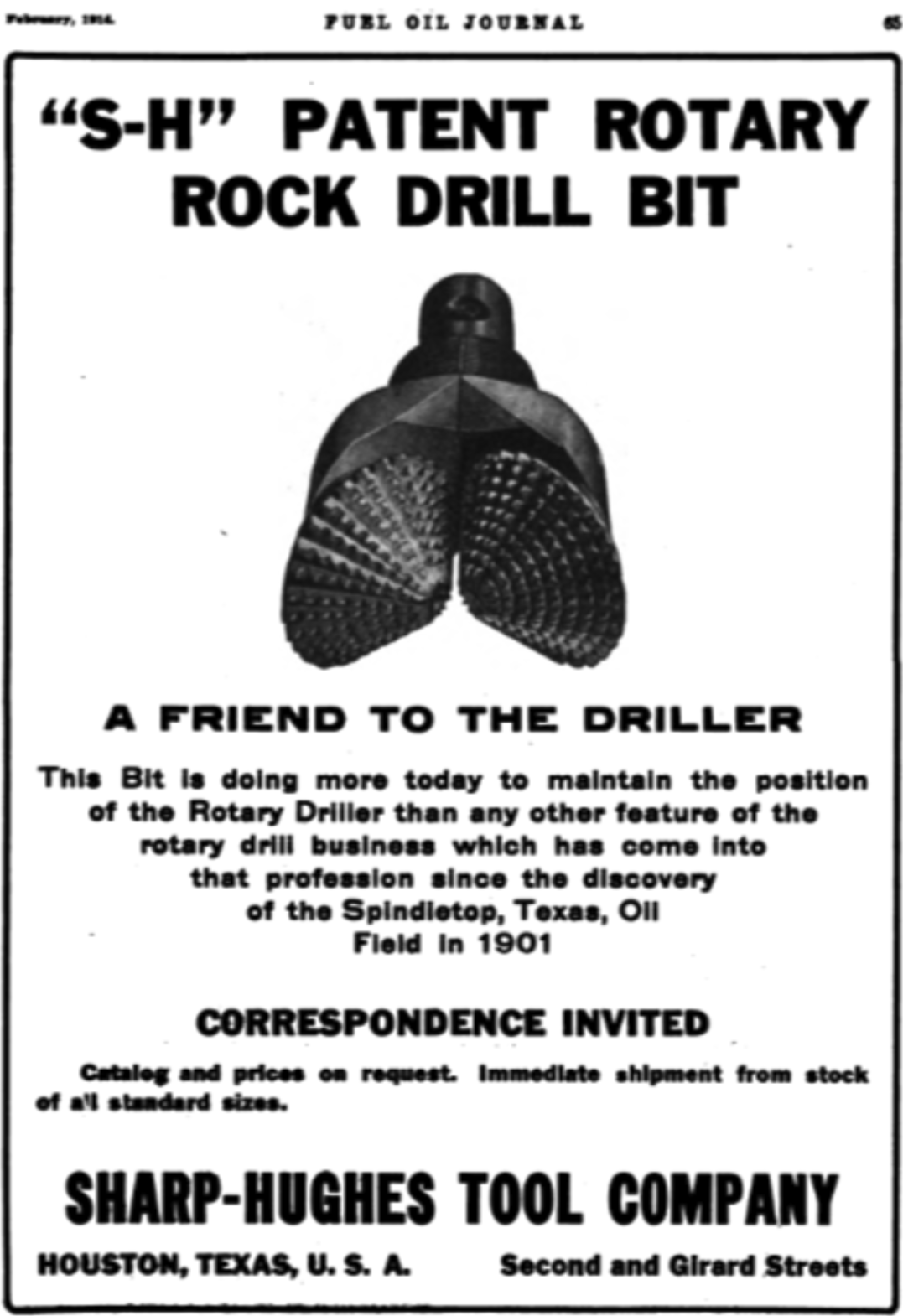 |
Spindletop makes rotary drilling with circulating fluid the standard: 1,139 ft, 100,000 barrels a day. In 1909 Hughes patents the rolling-cone cutter. Every bit on this page runs the same design, just more cutters on a bigger body. Source: Sharp-Hughes Tool Company advertisement, Fuel Oil Journal, February 1914. |
|
| 1963 | 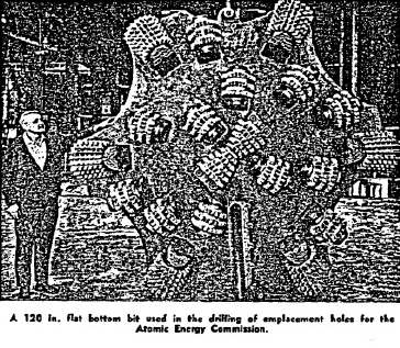 |
The Limited Test Ban Treaty moves US testing underground. The AEC begins drilling 72-inch holes to 4,000 feet; big-hole footage grows from 5,000 ft a year in 1959 to 117,000 ft in 1967. Pictured: a 120-inch flat-bottom emplacement bit. [1, 4] Source: Allen, J. H., “Drilling Large Diameter Holes,” Australian Oil and Gas Review, June 1968 [1]. |
|
| 1968 |  |
Holes of 36 to 144 inches were practical; the deep ones reached 5,600 and 6,000 feet. The collar stack above a 120-inch bit weighed about 480,000 pounds and acted as a plumb bob: under one foot of drift at 4,000 feet. A 54-inch string to 5,600 feet, about five million pounds, run on hydraulic jacks. [1] Source: NNSA/AEC photo library. |
|
| 1969 | 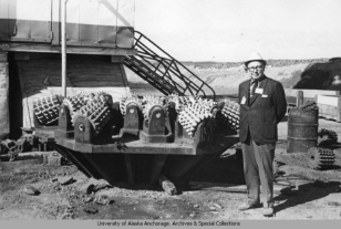 |
An AEC official beside a bit from the Amchitka emplacement-hole program. The finished hole: 90 inches in diameter to 6,000 feet, drilled by Parker Drilling on reverse circulation air lift. Still the deep-and-wide benchmark. [2] Source: University of Alaska Anchorage, Archives and Special Collections. |
|
| 1981 | 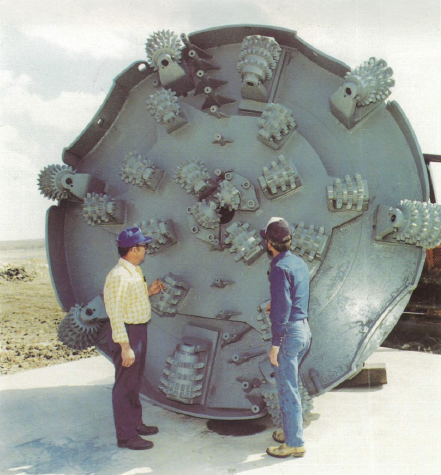 |
Hughes builds the CSD-300, a purpose-built shaft rig rated for 20-foot holes to 3,000 feet. The 12-foot bit body shown was the smallest it could run. The equipment kept scaling after the test program peaked. [3] Source: Grisham, J., “New Rig Has Heavy Oil Potential,” Drilling Contractor, April 1981 [3]. |
|
| 1974-2026 | 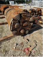 |
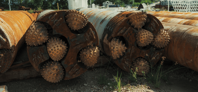
The method never stopped. Reverse flood reached Florida's deep injection wells by 1974, in the federal record. One Fort Myers contractor, Youngquist Brothers, has drilled 163 of Florida's 177 Class I wells: tops 54 to 74 inches, finals 20 to 36 inches, depths to 10,000 feet, all state-verified. A wide, deep hole is a routine municipal purchase. [6, 8, 11, 14] Source: Contractor yard, modern large-diameter hole openers. |
|
1. The three tests
Measured against oil and gas practice, the only drilling record most readers know, a borehole several feet across and cased to a mile looks radical. Speed and success in drilling a large-diameter well stands or falls on three tests: holding the hole vertical, cleaning the cuttings out of it, and setting the casing.
Vertical: Holes of 72 to 120 inches were drilled to between 4,000 and 6,000 feet in the 1960s and held to less than one foot of horizontal displacement at 4,000 feet [1, 2]. Clean: A 60-inch hole advanced 200 feet in 24 hours with no pilot hole [1]. Cased: A 54-inch string weighing about 5,000,000 pounds was run to 5,600 feet on hydraulic jacks [1].
The misconception to clear first is that this is a capability that existed once and was lost. The customer that ordered the largest holes went away in 1992 [5], and the industries that had used the method before the test program, mine shafts and deep disposal wells, kept drilling with it and are drilling with it now [6, 7, 8]. What changed is economic, and Section 4 puts numbers on it.
2. Built in a decade, 1959 to 1970
Before the late 1950s, large holes were mostly improvisation. Contractors drilled a conventional pilot hole, then reamed it in passes to 36, 48, or 60 inches. Conventional drill pipe could not move enough fluid to clean a big hole in a single pass, so hole cleaning, not rock cutting, was the limiting factor [1]. The source of that limit was the circulation system, not the pilot-and-open sequence itself, which returned later upon development of a circulation system that could keep up (Section 3).
Purpose-built tools arrived in 1959 and 1960: large-bore swivels, 13-3/8-inch drill pipe, and stacked cast iron drill collar weights [1]. In 1960, a 710-foot uranium mine ventilation shaft was reamed from 15 inches to 90 inches in a single pass. By 1961, a 60-inch hole advanced 200 feet in 24 hours with no pilot hole at all [1]. Field results settled a design argument: a heavy, stabilized bottom hole assembly drilled straighter than any pilot hole could. Drill collar assemblies approaching 480,000 pounds acted as a plumb bob, and holes were completed with less than one foot of horizontal displacement at 4,000 feet [1].

Exhibit 1. Growth of the big-hole industry. All figures from Allen, 1968 [1].
| Year | Measure | Figure |
| 1959 | Annual footage, holes over 36 in. | ~5,000 ft (ten holes) |
| 1967 | Annual footage, holes over 36 in. | 117,000 ft |
| 1959 to 1968 | Cumulative footage over 36 in., North America | 500,000 linear ft |
| 1968 | Largest diameter considered practical | 144 in. |
| 1968 | Heaviest casing string reported (54 in. x 5,600 ft) | ~5,000,000 lb, run on hydraulic jacks |
Exhibit 2. Named wells of the era. Years shown as ranges where the accession gives an era rather than a completion date; “not stated” marks fields the source does not carry. The 1960 to 1968 rows are from Allen 1968 [1]; the three 1965 to 1970 test emplacements are from Allen 1976 [2].
| Year | Location and purpose | Hole diameter | Depth | Contractor |
| 1960 | Uranium mine ventilation shaft | 90 in. (reamed from 15 in. pilot) | 710 ft | not stated |
| 1963 to 1968 | Mine shaft | 72 in. | 2,790 ft | not stated |
| 1963 to 1968 | Mine shaft | 108 in. | 1,435 ft | not stated |
| 1963 to 1968 | Mine shaft | 124 in. | 935 ft | not stated |
| 1963 to 1968 | Mine shaft | 130 in. | 520 ft | not stated |
| 1963 to 1968 | Nuclear test emplacement series, Nevada | 72 in. | 4,000 and 5,000 ft | multiple |
| 1965 to 1970 | Test emplacement, Amchitka Island, Alaska | 90 in. | 6,000 ft | Parker Drilling |
| 1965 to 1970 | Test emplacement, central Nevada | 120 in. | 5,600 ft | Shaft Drillers |
| 1965 to 1970 | Test emplacement, central Nevada | 120 in. | 4,800 ft | Loffland Brothers |
3. The method: reverse flood
Holes this size outran conventional mud pumping. In conventional circulation, fluid travels down the drill pipe and back up the annulus between pipe and hole wall, so as the hole widens, the pump rate required to keep cuttings moving grows with it until it becomes impractical; that is the single-pass cleaning limit of Section 2 [1]. Think of a dental cleaning: water sprays in while a small suction wand pulls water and debris out through a narrow tube, and the mouth stays full throughout. A reverse flood rig does the same to a borehole. Compressed air lightens the fluid inside the drill pipe, and the heavier fluid standing in the hole pushes water and cuttings up the pipe's bore to surface; the hole stays full, and that standing column is the well control. Because the returns travel up a fixed bore, the velocity carrying the cuttings does not fall as the hole gets wider, which is why one circulation package served 72-inch and 120-inch bits alike [1, 2].
The method has carried different names as it moved between industries: reverse circulation air lift in the AEC-era literature [1, 2] and in the federal record of early Florida deep disposal wells [6], dual-tube flooded reverse circulation in modern shaft work [7]. This paper uses reverse flood throughout.
4. Why oil and gas left it behind
An oil or gas well delivers its product through a small bore conduit. Beyond the diameter needed to set casing, a bigger hole adds excavated volume and cost without adding production: rock removed grows with the square of diameter, while flow into a vertical well grows only with the logarithm of hole radius, so doubling the standard 8.5-inch production hole quadruples the rock for about a ten percent gain in flow [16, 17]. The industry's purchasing says the same thing: Permian operators grew average laterals from under 4,000 feet in 2010 to over 10,000 feet in 2022 [19] while the production hole held at the standard 8.5 inches [18]. Allen made the comparison himself: a 120-inch hole to 6,000 feet is comparable in excavated volume to 600,000 feet of 12-inch hole, and he cautioned that comparing big hole drilling to oil well drilling is not realistic [1]. The oilfield supplied the rigs, the contractors, and the crews, but the paying customers were the AEC and the mining industry, not petroleum production.
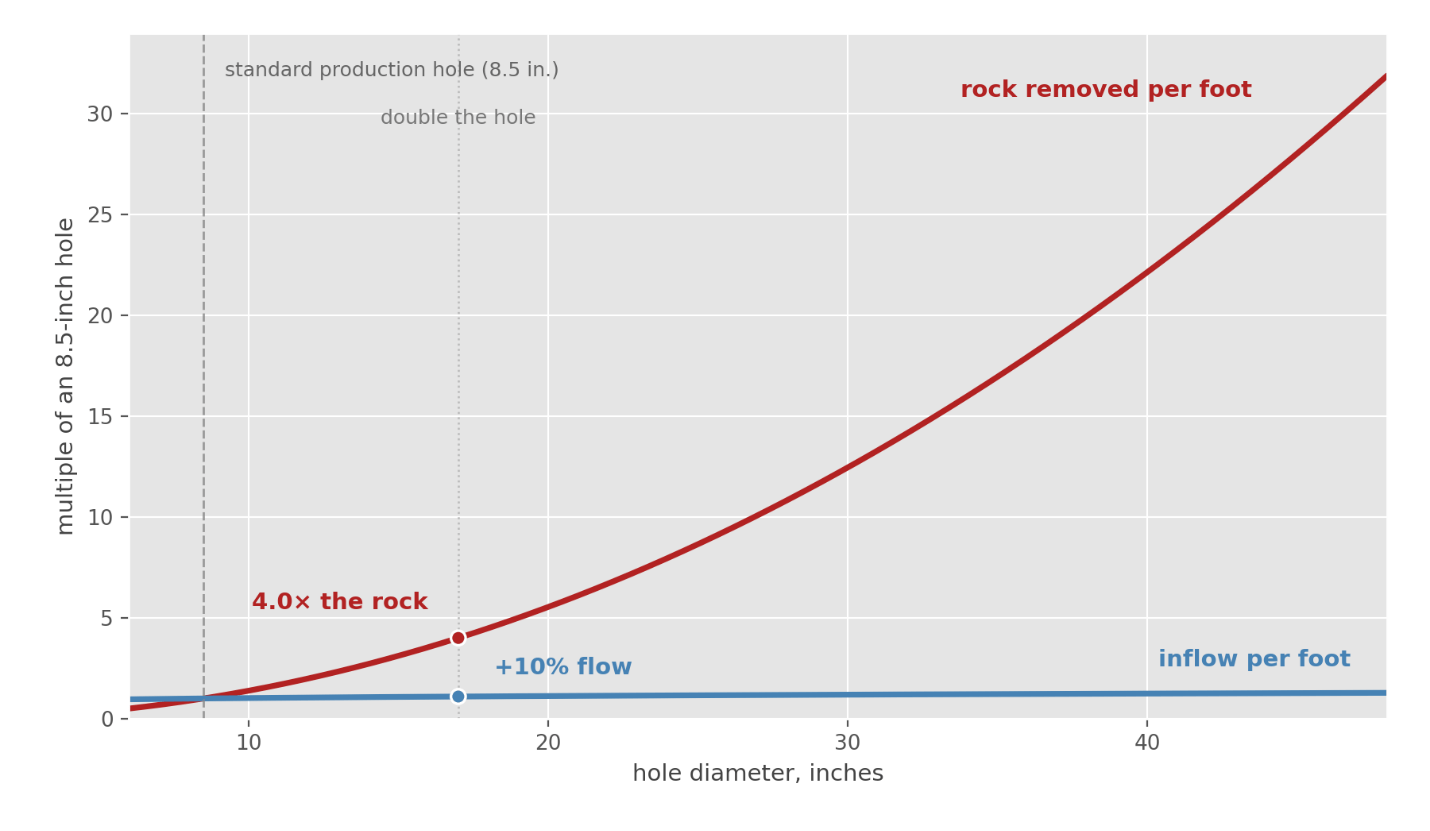
Exhibit 3. The arithmetic that keeps oil wells narrow. Cost of the hole and oil produced, indexed to a standard 8.5-inch production hole (8.5 in. = 1.0). Rock volume removed grows with the square of diameter; steady-state inflow to a vertical well follows radial Darcy flow at a 1,000 ft drainage radius, so doubling the hole to 17 inches quadruples the rock for about a ten percent gain in flow. Sources: geometry; [16, 17]; hole-size convention [18].

5. Case study one: Florida's deep injection well industry
The method reached Florida's deep disposal work while the test program was still running. A City of Sarasota test well for wastewater disposal, drilled from July 1973 to November 1974, ran conventional mud rotary to 1,146 feet and reverse circulation air lift from there to a total depth of 3,513 feet; the U.S. Geological Survey published the record [6].
The cleanest continuity evidence in the record is a Fort Myers contractor, Youngquist Brothers, Inc. By the company's own published count, it has built over 92 percent of Florida's Class I deep injection wells, 163 of 177, with final casings up to 36 inches by 0.500-inch wall approaching 3,000 feet, and exploratory wells past 10,000 feet [11]. These are the wells that place treated municipal wastewater below the drinking water aquifers under the Underground Injection Control rules of Chapter 62-528 [15], and they telescope: a wide hole at surface, stepping down through cemented casing strings to a final string a fraction of the top diameter. The databases below record that final, smallest string; the hole above it is larger at every step.
Exhibit 4. The modern record in three public databases.The first two databases are filtered to Youngquist Brothers as driller or contractor of record; the third is a statewide inventory whose records do not carry a contractor field.
| Database | Records | Years | Depths | Diameters | Source |
| Florida Geological Survey boreholes, driller of record Youngquist | 213 wells | 1983 to 2026 | to 10,000 ft | not recorded | [8] |
| SWFWMD well construction permits, contractor Youngquist | 279 permits | 1978 to 2012 | to 3,520 ft | casing to 34 in. | [10] |
| FDEP UIC monitoring well inventory, wells over 20 in., statewide | 17 wells | not dated in inventory | 60 to 3,150 ft | 22 to 54 in. | [9] |
The FGS extract shows completions in 42 of the 44 years from 1983 through 2026; 56 of the SWFWMD permits carry casing of 12 inches or larger [8, 10].
Four wells show the shape of the business. At Miami-Dade County's South District plant, the construction manager's published program for three injection wells runs 64 inch pit casing, 54 inch surface casing, 44 and 34 inch intermediates, and 24 inch final casing set near 3,200 feet, drilled by Youngquist under a county construction contract [14]. The City of St. Petersburg took 30-inch casing on injection wells in the mid 1980s [10]. The Polk Regional Water Cooperative's well reached 8,022 feet in 2024 [8], on about 3,700 feet of 20-inch seamless final casing [13], a project the contractor announced publicly [12]. And in 2026 the register shows a 3,350-foot injection well in St. Lucie County [8]. Where the public record shows a full program, the top strings run 54 to 64 inches [14].
These wells are drilled on reverse flood. Florida's UIC rules require driller's logs, daily job reports, and an engineer-certified final construction report for every Class I well, filed with the Department [15].
This is the wide hole as a routine municipal purchase: specified by consulting engineers, bid competitively, drilled year after year for four decades, and verified by a state regulator.
6. Case study two: shaft drilling for mining and construction
The mining thread never broke. Between 1900 and 1960, over thirty large diameter mine ventilation and access shafts were rotary drilled in Germany and Holland on reverse circulation air lift [2]. Allen's 1968 list included a 72-inch hole to 2,790 feet, a 108-inch hole to 1,435 feet, and a 130-inch hole to 520 feet drilled for mine ventilation and access [1]; the 130-inch holes of the era include a southern Louisiana salt mine shaft drilled by North American Drilling in the early 1960s [2].
The modern record reads the same way. In 2015, a Boart Longyear crew drilled a 60-inch ventilation shaft to 550 feet through two aquifers at a southwest Wyoming coal mine, in a single pass, in about four weeks, on reverse flood (Boart's term: dual-tube flooded reverse circulation), on a site where lost circulation zones ruled out raise boring; the shaft was cased with 54 inch, half-inch wall casing cemented in place [7].
7. The record in one exhibit
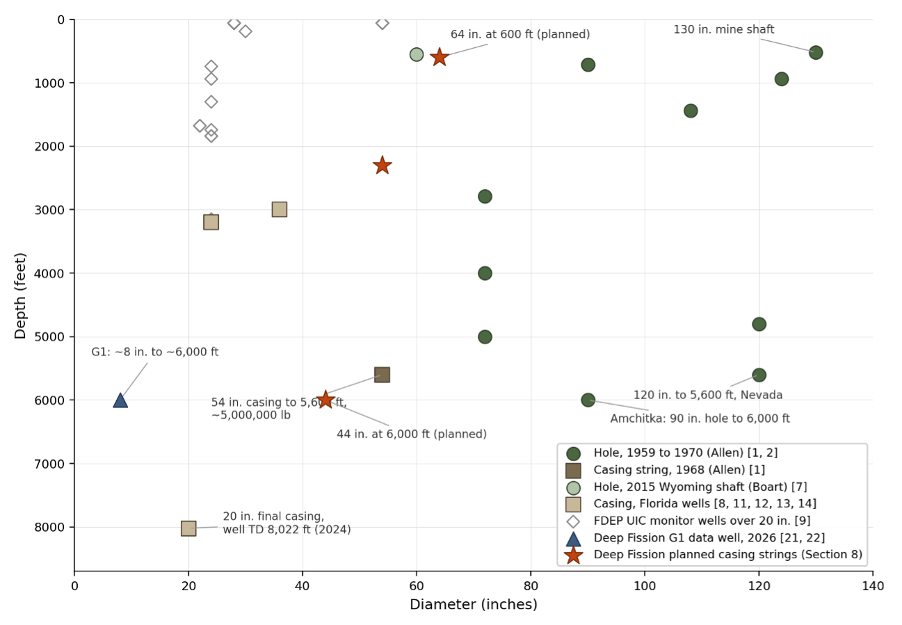
Exhibit 5. Depth and diameter: the drilled record and the Deep Fission plan. Circles are drilled hole diameters; squares are casing strings; open diamonds are the 17 FDEP-inventoried UIC monitor wells over 20 inches; the triangle is Deep Fission's G1 data acquisition well, drilled June 2026; stars are the planned strings of Section 8.
Holes of 90 to 120 inches were drilled past 4,800 feet more than fifty years ago, straight to within one foot at 4,000 feet [1]. The heaviest string on the record, 54 inches to 5,600 feet, was run in the 1960s [1]. Today's commercial work runs final strings of 20 to 36 inches to depths of 3,000 to more than 8,000 feet [8, 11, 12, 13] under top strings of 54 to 64 inches [14]. The two clusters bracket the planned Deep Fission strings on both axes: every planned diameter has been exceeded at a comparable depth, and every planned depth has been reached at a smaller diameter, with the 1968 casing record sitting within 400 feet and 10 inches of the deepest planned string. What has not been drilled is the exact combination. Oil and gas made the same kind of step on the axis it gets paid for: Permian laterals ran from under 4,000 feet to over 10,000 in twelve years while hole diameter never moved [19]. Extending a proven envelope along one axis is routine drilling practice. The step from the record to the plan is a matter of degree, not a new capability.
8. The Deep Fission well
Deep Fission's first Kansas well is public record. The company began drilling its first data acquisition well at its Parsons site in March 2026, to a planned depth of approximately 6,000 feet at roughly eight inches of diameter [21], and reported the well complete in June 2026 [22]. A second well, to about 2,500 feet, is planned to demonstrate deep deployment of major components, including lowering a prototype reactor [22].
The commercial well plan telescopes the way Florida's injection wells do: 64-inch casing at 600 feet, 54-inch casing at 2,300 feet, 44-inch casing at 6,000 feet.
Each string has a neighbor on the record. A 64-inch top string matches the pit casing of the Miami-Dade program [14]. A 54-inch string at 2,300 feet sits 3,300 feet above the 54-inch string run in 1968 [1]. A 44-inch string at 6,000 feet is about half the diameter drilled to that depth at Amchitka [2].
Bibliography
1. Allen, J. H. “Drilling Large Diameter Holes.” Australian Oil and Gas Review, June 1968. U.S. Nuclear Regulatory Commission ADAMS accession ML040480471.
2. Allen, J. H. “A Review of Reverse Circulation Air Lift Methods for Big Hole Drilling.” Society of Mining Engineers preprint 76-AU-67; reprinted in World Mining, January 1976. U.S. NRC ADAMS accession ML040480471.
3. Grisham, J. “New Rig Has Heavy Oil Potential.” Drilling Contractor, April 1981. OSTI ID 6324269. Reprint bound with Santa Fe Shaft Drilling Company brochure material.
4. Treaty Banning Nuclear Weapon Tests in the Atmosphere, in Outer Space and Under Water (Limited Test Ban Treaty). Signed Moscow, August 5, 1963; entered into force October 10, 1963. U.S. National Archives, Milestone Documents, archives.gov/milestone-documents/test-ban-treaty; U.S. Department of State, Office of Treaty Affairs.
5. Los Alamos National Laboratory. “Divider, 30 Years Later.” National Security Science, November 2022, lanl.gov. Lawrence Livermore National Laboratory, “30 Years Later, Hunters Trophy Participants Recall LLNL's Final Underground Nuclear Test,” September 2022, llnl.gov. National Nuclear Security Administration, Administrator's statement on the 30th anniversary of Divider, September 23, 2022, energy.gov.
6. Sutcliffe, H. “Hydrologic Data from a Deep Test Well, City of Sarasota, Florida.” U.S. Geological Survey Open-File Report 79-1275, 1979. DOI 10.3133/ofr791275.
7. Boart Longyear. “Boart Longyear Team Uses Dual-Tube Flooded Reverse Circulation Technique to Drill 60-Inch Shaft Through Loss Circulation Zones at Wyoming Coal Mine.” Press release, February 26, 2015, boartlongyear.com. Also reported in The Driller, March 5, 2015, thedriller.com/articles/89939.
8. Florida Geological Survey. Borehole database, records with driller of record Youngquist Brothers, Inc. Accessed July 2026. 213 records, 1983 to 2026.
9. Florida Department of Environmental Protection. Underground Injection Control monitoring well inventory, wells greater than 20 inches in diameter. Accessed July 2026. 17 records.
10. Southwest Florida Water Management District. Well Construction Permits database, records with contractor Youngquist Brothers. Accessed July 29, 2026. 279 records, 1978 to 2012, with per-record permit pages at swfwmd.state.fl.us.
11. Youngquist Brothers, LLC. Company website, youngquistbrothers.com. Accessed July 29, 2026.
12. Youngquist Brothers. Company announcement, LinkedIn, second half of 2023: 8,000-foot Cretaceous well for the Polk Regional Water Cooperative. linkedin.com/company/youngquist-brothers.
13. Polk Regional Water Cooperative. American Iron and Steel project-specific waiver request to the Florida Department of Environmental Protection, July 31, 2023. Hosted at epa.gov.
14. GFT Inc. Project record, South District Wastewater Treatment Plant Injection Wells, Miami-Dade County. gftinc.com. Accessed July 29, 2026.
15. Florida Administrative Code, Chapter 62-528, Underground Injection Control. Rules 62-528.430, 62-528.440, 62-528.450.
16. Dake, L. P. Fundamentals of Reservoir Engineering. Elsevier, 1978.
17. Craft, B. C., and M. F. Hawkins. Applied Petroleum Reservoir Engineering. Prentice-Hall, 1959.
18. Lowry, T. S., et al. GeoVision Analysis Supporting Task Force Report: Reservoir Maintenance and Development. Sandia National Laboratories, SAND2017-9977, 2017. DOI 10.2172/1394062.
19. U.S. Energy Information Administration. “Average Lateral Length in the Permian Basin Continues to Increase.” Today in Energy no. 54079, September 30, 2022; underlying data Enverus.
20. “Mining for Kern River's Oil.” Pacific Oil World 73, no. 10 (1980), OSTI 6069292; “Hot Plate at Kern River” (1982), OSTI 5503703.
21. Deep Fission, Inc. “Deep Fission Kicks Off Historic Borehole Drilling for First-of-a-Kind Nuclear Project.” Press release, March 10, 2026. deepfission.com.
22. Deep Fission, Inc. “Parsons, KS: Deep Fission Nuclear Project Site.” Project page reporting the G1 data acquisition well complete to approximately 6,000 feet as of June 2026, and a second well of approximately 2,500 feet for component deployment. deepfission.com/sites/parsons. Accessed July 29, 2026.
23. Ballance, W. C. "Hydraulic Tests in Hole UA-1 and Water Inflow into an Underground Chamber, Amchitka Island, Alaska." U.S. Geological Survey Open-File Report 70-16, 1970. DOI 10.3133/ofr7016.
Forward Looking Statements
This press release contains forward-looking statements within the meaning of the federal securities laws. Forward-looking statements include, but are not limited to, statements regarding Deep Fission’s business strategy, technology development plans, potential commercial deployments, potential demand represented by non-binding LOIs, expected regulatory activities, planned project milestones, potential commercialization, potential revenue recognition, and the timing, feasibility, scalability, safety, and performance of the Company’s technology. These statements are based on current expectations and assumptions and are subject to risks and uncertainties that could cause actual results to differ materially from those expressed or implied.
Important factors that may cause actual results to differ materially include, among others, risks related to the Company’s early stage of development; the non-binding nature of the LOIs; the Company’s ability to negotiate and enter into definitive commercial agreements; technical, engineering, drilling, construction, regulatory, licensing, financing, supply chain, and deployment risks; the Company’s ability to obtain required approvals from the NRC, DOE, and other governmental authorities; market adoption of the Company’s technology; and the other risks described under “Risk Factors” and “Cautionary Note Regarding Forward-Looking Statements” in Deep Fission’s filings with the Securities and Exchange Commission.
Forward-looking statements speak only as of the date of this press release. Deep Fission undertakes no obligation to update any forward-looking statements, except as required by law.
Company News